If you’re reading this, chances are you’re either integrating a Seya-Namioka flat-field concave holographic grating into your spectroscopy setup for the first time, or you’ve noticed uncharacteristic drift, signal noise, or wavelength calibration errors that you can’t trace to your detector or light source. As someone who’s spent the last 12 years as a supplier specializing in these exact gratings—working with everyone from university astrophysics labs to industrial quality control teams checking semiconductor wafers—I can tell you that 80% of the performance issues we get called out for aren’t flaws in the grating itself. They’re environmental missteps that often get overlooked in the rush to calibrate equipment or meet tight project deadlines. Let’s break down the non-negotiable environmental requirements for using a Seya-Namioka flat-field concave holographic grating, rooted in both physics and decades of hands-on support. Seya-Namioka Flat-Field Concave Holographic Grating

First, let’s ground this in what makes these gratings unique, because their environmental sensitivity ties directly to their design. Unlike ruled gratings, which are mechanically etched with grooves, holographic Seya-Namioka gratings are created using laser interference to pattern grooves on a concave substrate, then coated with a thin layer of aluminum or gold for reflectivity. The flat-field correction is a key feature: unlike traditional concave gratings that require a curved detector, these focus light into a flat plane, simplifying setup for end users. But that precision comes at a cost: the groove spacing is measured in nanometers, and the substrate curvature is aligned to within micrometers, so even minor changes to temperature, humidity, or vibration can shift that alignment enough to throw off your entire spectrum.
Let’s start with temperature stability—this is the single most important environmental factor, period. I’ve seen customers get away with ±1°C temperature swings for other optical components, but Seya-Namioka gratings demand far tighter control. Here’s why: most grating substrates are made of fused silica (silicon dioxide) for its low thermal expansion, but even fused silica has a coefficient of thermal expansion (CTE) of approximately 5.5 × 10⁻⁷ per °C. That means for a standard 50mm-diameter grating, a 1°C temperature change will expand or shrink the substrate by 27.5 nanometers. If your grating has a groove density of 1200 grooves per mm (a common choice for UV spectroscopy), that’s a shift of 0.015 nm per groove in the groove spacing. Multiply that across the entire grating, and you’re looking at wavelength calibration errors of up to 1 nm for a 200–400 nm UV scan—enough to misidentify atomic emission lines or skew material analysis results.
Now, let’s get specific: what’s the acceptable range? For routine use in UV-VIS spectroscopy, we recommend maintaining a constant temperature between 18°C and 25°C, with a maximum gradient of ±0.2°C over any 4-hour period, and no more than ±0.1°C per hour. For high-precision work, like analyzing trace elements in pharmaceuticals or astronomical spectroscopy where wavelength accuracy is critical, you’ll want to tighten that even more: ±0.05°C per hour, with no long-term drift exceeding 0.1°C over 24 hours. The mistake many new users make is only calibrating their setup at room temperature, then letting the lab heat or cool as the day goes on. Even if you don’t notice it, a 0.5°C swing between morning and afternoon use is enough to add systematic error to your data. I once worked with a team at a environmental testing lab that spent three months troubleshooting a soil lead analysis before they realized their lab’s HVAC unit was cycling every hour, creating just enough temperature shift to throw off their Seya-Namioka grating’s calibration. We added a small in-line temperature controller to their grating mount, and their error dropped by 90% almost immediately.
Next up: relative humidity. This is a second factor that’s easy to ignore, especially if your lab is in a dry climate, but it can cause two different types of damage or performance issues. First, high humidity—anything above 60% relative humidity (RH) at temperatures above 20°C—can lead to condensation forming on the grating surface, even if you don’t see it. Condensation eats away at the thin metal coating (aluminum or gold) over time, leading to reduced reflectivity, especially in the UV range where aluminum’s performance is most critical. I’ve had customers send back gratings that looked fine under a microscope but had 30% lower UV reflectivity after two years, only to find their lab’s RH hovered at 65% year-round. We now add a hydrophobic coating as a standard for orders going to dry climates, but even that won’t protect against prolonged high humidity.
Low humidity is equally problematic, though. When RH drops below 30%, static electricity builds up on the grating’s surface, and it can attract tiny dust particles that are smaller than a human hair. Those dust specks don’t just block light—they cause scattered diffraction, creating background noise in your spectrum that can mask weak signals, like the emission line of a rare earth element or a faint absorption band in a biological sample. We’ve found that for most applications, keeping RH between 30% and 50% is the sweet spot. It’s low enough to prevent condensation and static, high enough to avoid static-related dust buildup, and easy to maintain with standard lab humidifiers or dehumidifiers. The only exception is if you’re working in a vacuum environment—wait, that’s a whole separate case. If your setup is for vacuum UV spectroscopy (VUV), RH is irrelevant because the vacuum will remove moisture entirely, but you’ll need to account for thermal expansion differently in a vacuum, as the mount can shift as pressure changes.
Vibration is the third big one, and it’s often the most disruptive because it’s not always obvious. Seya-Namioka gratings are aligned to within micrometers of their mount, and even tiny vibrations can shift the groove alignment or tilt the grating just enough to cause spectral blur. What counts as problematic vibration? If you’re in a lab that’s on a upper floor, next to a centrifuge or a vacuum pump, or in a building near a busy road or train line, you might be getting vibration levels of 1 mm/s or higher in the 10–1000 Hz range. For most routine spectroscopy, vibration levels below 0.1 mm/s at 50 Hz are acceptable. But for high-resolution work, like measuring the fine structure of atomic lines, you need to get that down to below 0.02 mm/s.
The key here isn’t just about isolating the entire setup (though that helps)—it’s about isolating the grating mount specifically. I always recommend that customers mount their Seya-Namioka grating on an air isolator or a vibration-damping optical table, not a standard breadboard. Even if your optical table is rated for low vibration, if you have a motorized filter wheel or a detector that’s mounted directly on the same table, it can create small micro-vibrations that affect the grating. Another trick we share with all our customers: if you use a chopper or shutter in your setup, make sure it’s mounted on the opposite side of the table from the grating, not adjacent, to avoid cross-vibration. I once had a customer working at a university that had their Seya-Namioka setup next to a maintenance lab where they tested hydraulic tools. They’d spend weeks troubleshooting their Raman spectra, and the problem fixed itself only when the maintenance crew moved their tools to a different building. Vibration is sneaky, but it’s solvable with simple isolation steps.
Wait, there’s also the issue of outgassing, especially if you’re using your grating in a sealed or vacuum system. Holographic gratings have a polymer adhesive layer used to bond the grooved substrate to the mount, and if that adhesive is exposed to high temperatures or a vacuum over long periods, it can outgas volatile compounds that condense on the grating’s surface. That condensation isn’t just water vapor—it’s tiny organic molecules that can scatter light or even etch the groove surface over time. For any setup that operates at pressures below 1 Torr, or at temperatures above 40°C, you need to make sure your grating is baked out before installation, or use a grating with a low-outgassing adhesive. We test all our gratings for outgassing per ASTM E595 standards, so if you order a grating from us for vacuum use, we’ll include a certificate confirming its outgassing rate is below the 1% total mass loss required for space or high-vacuum applications.
Let’s also address a common myth: people think Seya-Namioka gratings need to be kept in a nitrogen-purged environment, but that’s only true for very specific, long-term storage, not routine use in a lab. Nitrogen purging is a good idea if your setup is in a dusty industrial environment where RH can’t be controlled, but for most academic or research labs, keeping RH and temperature within the ranges I mentioned is enough. Nitrogen purging adds unnecessary cost and complexity, and I’ve never seen it fix a performance issue that could be solved by basic environmental control.
Now, let’s talk about how to implement these requirements, because I don’t want this to be just a list of numbers—you need actionable steps. First, invest in a calibrated temperature and RH monitor that takes readings every 15 minutes, not just once a day. Cheap desktop monitors can be off by 1–2°C, which is enough to skew your data. Place the monitor within 10 cm of the grating mount, not near a vent or a window, where readings will be skewed. For vibration, if you can’t afford an air-isolated optical table, add a layer of rubber vibration pads between your grating mount and the breadboard—this simple fix can cut micro-vibration by 50% or more.
I’ve seen too many customers cut corners on environmental control to save money or time, only to end up paying more in lost data, repeat calibrations, or replacement gratings. A well-controlled environment doesn’t have to be expensive: a good temperature controller is a few hundred dollars, a basic RH monitor is under $100, and rubber pads cost almost nothing. The alternative, though, is weeks of troubleshooting, inconsistent results, and frustrated researchers.
If you’re struggling with performance issues related to your Seya-Namioka flat-field concave holographic grating, or you’re not sure what environmental controls you need for your new setup, feel free to reach out to discuss your specific application. We work with teams across industries to tailor our grating recommendations and provide guidance on optimizing your environment to get the best possible performance.
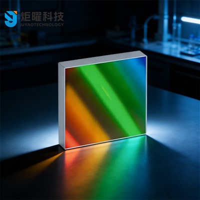
I recommend that you always keep in mind these requirements when integrating your grating into any system. Proper environmental control is half the battle for getting reliable, accurate spectroscopy results, and investing a little time and money upfront will save you a lot of headaches down the line.
Flat-Field Concave Holographic Grating References
- Palmer, E. (2014). Diffraction Grating Handbook, 7th ed. Newport Corporation.
- Loewen, E. G., & Popov, E. (1997). Diffraction Gratings and Applications. CRC Press.
- Smalley, R. E., et al. (2001). Environmental effects on holographic gratings for astronomical spectroscopy. Proceedings of SPIE, Vol. 4457, 112-123.
- ASTM E595-15e1. Standard Test Method for Total Mass Loss and Collected Volatile Condensable Materials from Outgassing in Atmosphere-Space Simulation. ASTM International.
- Basov, N. G., et al. (1995). Performance of Seya-Namioka monochromators with flat-field concave gratings for UV spectroscopy. Review of Scientific Instruments, 66(10), 4867-4872.
Jilin Juyao Technology Co., Ltd.
As one of the leading seya-namioka flat-field concave holographic grating manufacturers and suppliers in China, we offer a wide range of products with superior quality. Please feel free to wholesale customized seya-namioka flat-field concave holographic grating from our factory. Welcome to view our website for more information.
Address: Room 101, No. 2 Huiwen Road, Nanguan District, Changchun City, Jilin Province, China
E-mail: jyoptix@outlook.com
WebSite: https://www.jyoptix.com/
